
Key words: Rigid overhead conductor system, ROCS, Rigid conductor rail, FOCS, transition bar, drop tube, design, layout, installation, support spacing, scissor cross over, overlap, turnout, expansion joint
What is ROCS ?
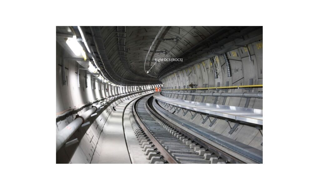
ROCS variously known as Rigid Overhead catenary System, Rigid Overhead Conductor System or Rigid Overhead Contact System is the most popular Overhead Current Collection System used in almost 100% of Metro Rail for collection of current by train pantograph in the underground tunnel section.
Difference between Rigid Overhead Catenary system (ROCS) and Flexible Overhead Catenary system (FOCS)
Rigid Overhead Catenary System (ROCS) has a single Rigid conductor rail unlike two or more flexible conductors used in conventional overhead current collection. Its construction and geometry is very simple compared to conventional FOCS.
Design and Installation of ROCS
The key elements of ROCS are Rigid Overhead Conductor Rail, Contact wire, Insulated Supports for the Rigid Overhead conductor rail, Overlaps, Anti-creep, Section insulator, ROCS Neutral Section and Transition section at junction of ROCS and Flexible Overhead Conductor System (FOCS). A single electrically continuous length of ROCS is generally around 500 m constructed out of connecting several lengths of Rigid Conductor Rail using splice joints. The function of each of these elements is described below:
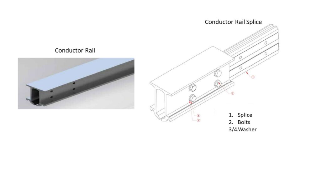
Rigid Overhead Conductor Rail
This element supports the contact wire from its groove with pinch action as shown here. The conductor rail is available in standard lengths. The choice of standard length depends on the extent of curved section and frequency of overlaps.
The main design consideration for the Rigid Overhead Conductor Rail are:
- Low linear weight to reduce sag permitting use of longer spans.
- Low height to reduce headroom requirement.
- High Moment of Inertia in the vertical plane.
- Sufficient current carrying capacity.
- Means to drain water which may enter the hollow conductor rail, to prevent corrosion.
- Strong pinch action on contact wire while allowing temporary widening without deformation or damage, for paying out the contact wire.
Conductor rail splice
The function of conductor rail splice is to join two standard lengths of rigid conductor rail to provide a mechanically rigid and electrically continuous joint.
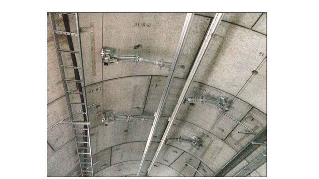
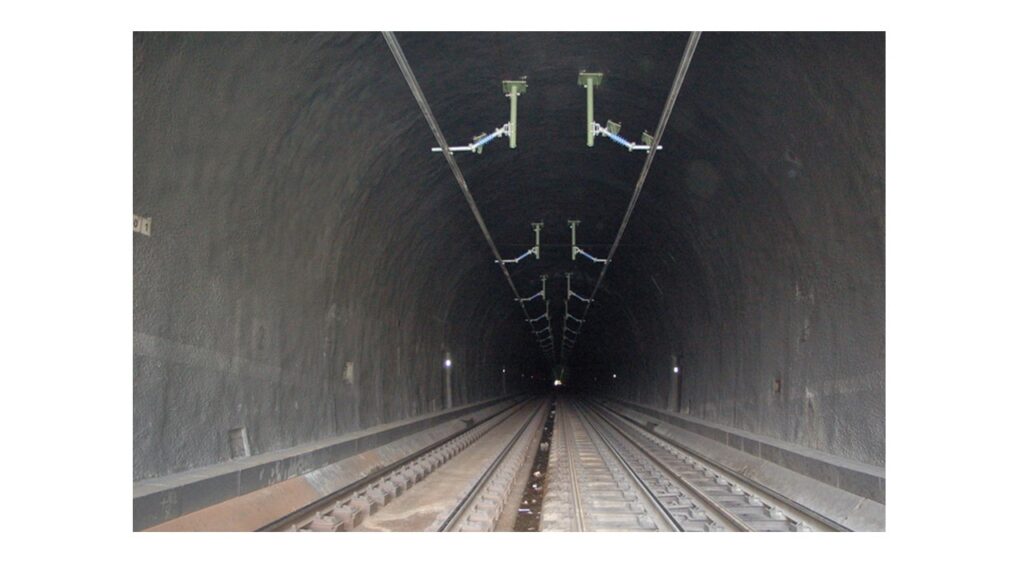
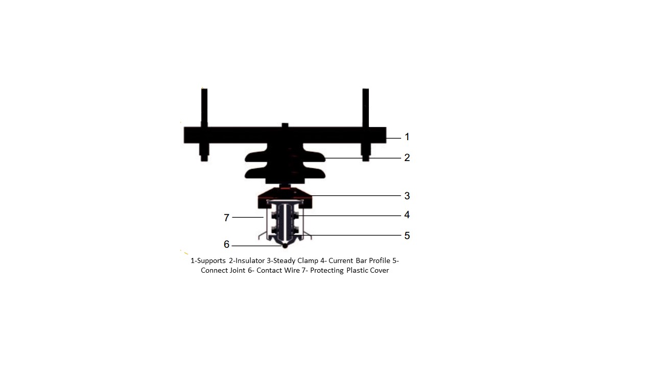
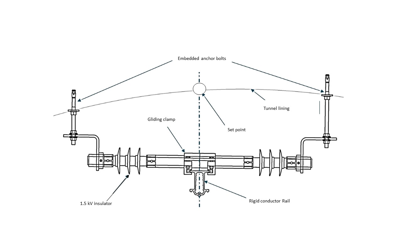
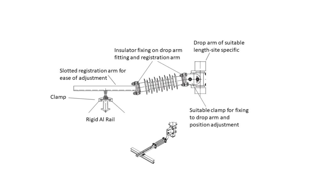
ROCS Supports
The ROCS support generally consists of one or two insulator depending on the support arrangement and traction voltage and means of holding the ROCS. The arrangement & positioning of ROCS support has to be carefully designed considering the geometry of tunnel inner lining; the clearance of live part of support from tunnel, and physical clearance of support arrangement from pantograph swept volume. Some typical arrangement commonly employed are shown in figures. The main consideration is design of ROCS support are:
- Requiring least headroom
- Able to accommodate the insulator and ROCS registration
- Able to allow movement of Rigid Rail due to thermal expansion/contraction.
- Permit some vertical movement when pantograph passes underneath.
- Provide a low contact resistance connection between contact wire and rigid conductor rail.
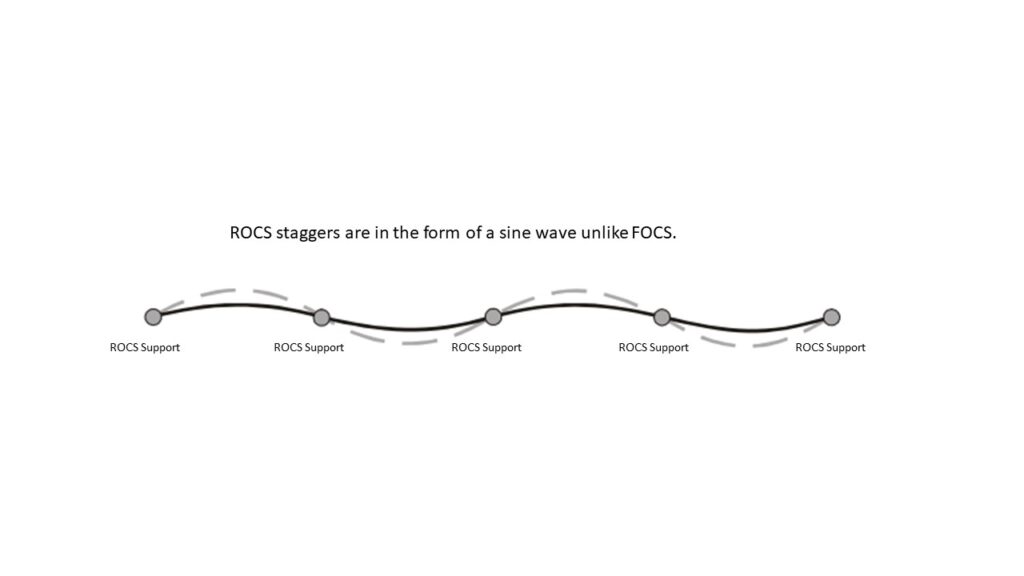
ROCS Staggers
Because of very small span length, the stagger in ROCS follow a sine pattern over a number of spans unlike in case of FOCS, where staggers on a tangent track alternate in each span. On curves, the stagger in ROCS are given to suit the track curvature. As there is no tension in ROCS, there are no pull off and push off supports.
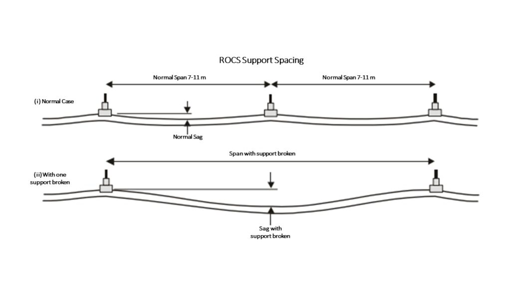
ROCS Support spacing
The support spacing of ROCS is considerably smaller compared to FOCS due to sag in the rigid conductor rail due to its self weight. Typical spacing of ROCS is in the range of 7-11 m only. Smaller spacing of ROCS permits higher speed. For maximum speed of 80-85 km/h in most MRTS, a support spacing of about 10-11 m is considered acceptable. For higher speeds up to 120 km/h, support spacing has to be reduced to about 7 m. The determination of maximum support spacing and maximum half tension length of ROCS is a matter of detailed design.
Considerations in placement of ROCS Supports
Following are some of the general considerations governing the location of ROCS supports and Span length:
1. ROCS supports should be avoided where there is significant leakage from tunnel.
2. ROCS supports should not be located below tunnel ventilation dampers.
3. ROCS supports should be located away from platform.
4. The drop tube or drop arm of ROCS support should be clear of pantograph swept zone. For the purpose of this, the lower end of drop tube should preferably be clearly above the contact wire level.
5. Where ROCS support is provided on OTE duct, it should have sufficient clearance.
6. On curves including curved section of ROCS at turnouts, the span should be limited to prevent excessive loading and allow smooth movement of ROCS at support registration.
7. ROCS support should not be provided towards side maintenance or emergency walkway.
7. In case of scissor cross over or turnouts, the ROCS support location is carefully located clear of pantograph swept zone.
8. ROCS support in transition zone are dictated from considerations of its particular design.
9. ROCS span in the overlap and anti-creep are governed by considerations given above.
10. ROCS feeding point clamps should preferably be near the ACC so that their movement due to thermal changes is minimum.
11. ROCS support should be so adjusted near feeding connection that the feeding clamps are not very far away from ROCS support and the cable length of connection permits free movement of conductor rail while at the same time remains well above the contact plane at all times.
12. ROCS support locations should not conflict with air nozzle installed for tunnel ventilation system.
12. The ROCS supports may have to be placed on both side of ROCS in case of overlaps and cross overs. The tunnel aerial earth wire for earthing the drop tubes on both side should cross below the track instead of above the ROCS. or
ROCS Overlaps
The maximum continuous length of ROCS is limited from thermal considerations.
Like FOCS, the ROCS also has two type of overlaps:
- Expansion Overlaps or Uninsulated Overlaps.
- Insulated Overlap or Sectioning Overlaps.
The expansion overlaps, also variously known as construction overlap or uninsulated overlap, are designed with a parallel run with normal air clearance between the overlapping length of ROCS as 100 mm, unlike in case of Insulated overlaps, also termed as sectioning overlaps, where the minimum air clearance for 25 kV AC is 400 mm. The Expansion overlaps are made electrically continuous by jumpering the two overlapping lengths. The Insulated overlaps are either open overlaps which remain electrically insulated by air gap unless bridged by passing pantograph or are normally bridged by a switchgear-which can be opened, if need be to electrically separate the two sections.
The ROCS overlaps have much smaller spacing, typically about 250-500 m compared to around 1500 m in case of FOCS, to limit the movement of ROCS due to temperature changes.
The overlaps are much shorter in length and are created by providing a ramp section at ends of in-run conductor rail sections. The location of Insulated overlaps has to be carefully designed taking account of the tunnel ventilation section, position of cross passages and normal stopping points or line or virtual stop signals to avoid any pantograph of train bridging an open Insulated overlap.
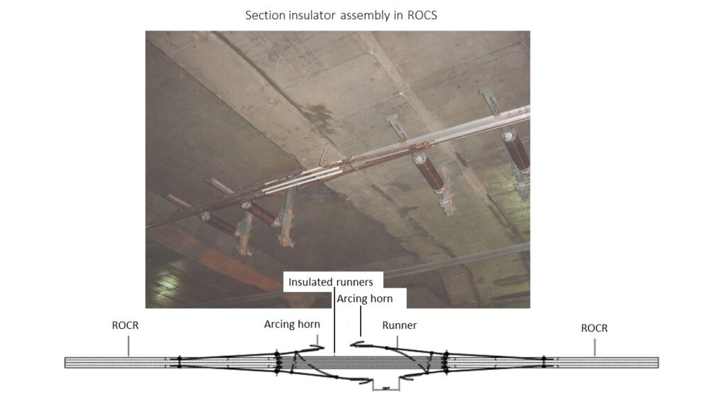
Section Insulator in ROCS
Sectioning in ROCS can be achieved by provision of Section Insulator assembly or by air gaps (Insulated overlaps).
The Section insulator for ROCS is similar to the section insulator for FOCS but is designed to be accommodated in the conductor rail unlike FOCS where it is integrated with contact wire and messenger wire. Sectioning achieved by provision of section insulator while having the advantage of requiring smaller length in comparison to air gap sectioning has a disadvantage in terms of requirement of higher headroom due to arcing horns projecting above the section insulator. The sectioning at scissor cross over is therefore often achieved by providing air gaps if the space (length) permits.
The Section insulator has to be so placed in cross overs so as to provide sufficient electrical and mechanical clearance from passing pantograph over adjoining different elementary section
Neutral section in ROCS
Several variety of neutral section design are used in ROCS. The design is mainly dictated by its ability of extinguish arc created at the transition zone between the live and dead and earthed or floating portion of neutral section. While some designs require an earthed central dead section so as to trip the feeder circuit breaker in case the arc is not quenched at the first overlapping zone of neutral section. The second design is based on extending the arc length so that it extinguished on its own. The second design obviously requires a longer track length to accommodate but has the advantage of preventing unnecessary tripping. The first type of design has the advantage of preventing damage to the ROCS and Pantograph in case the arc sustains.
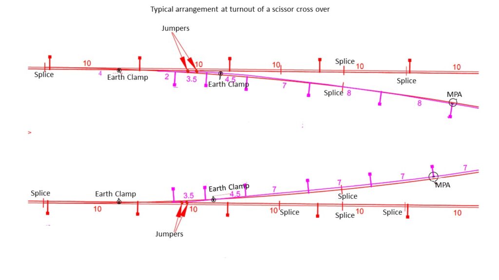
Arrangement at Turnouts & Scissors
At turnouts, the ROCS of two tracks generally follow the corresponding track geometry. The ROCS supports are placed such that they do not cross over the ROCS. The ROCS supports for cross overs and scissors are carefully planned and given staggers so as to accommodate the supports without infringing swept profile of pantograph moving on adjoining track.
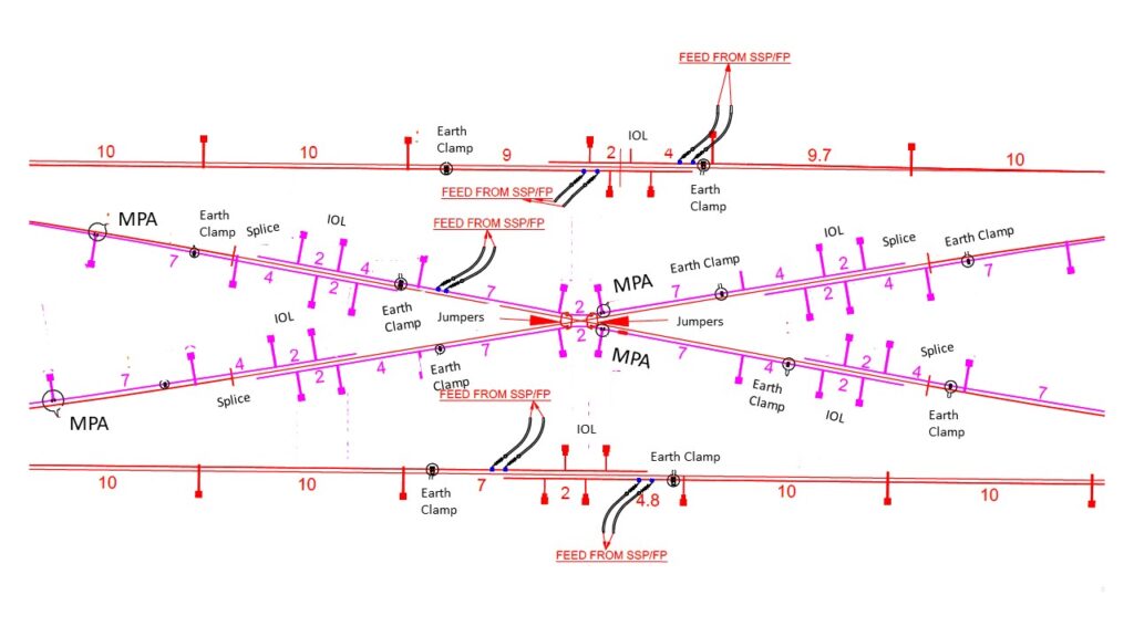
Feeder connections or Jumpers in ROCS
Feeder or Jumper connections in ROCS are provided keeping following points in view:
1. It should be close to ACC so that movement of Conductor rail at the jumper location is minimum.
2. The length of jumper cable should be sufficient to allow thermal expansion of Rigid Rail.
3. The jumper cable should be supported on insulators so as to have sufficient electrical clearance from nearest earthed parts or tunnel and does not transfer its weight or tension to ROCS.
Anti-creep or Mid Point Anchor (MPA)
An anti-creep support or a mid point anchor is necessary approximately in the middle of ROCS overlap length, to allow controlled thermal expansion of ROCS on either side of it. The ROCS is rigidly held at this support location to prevent any thermal movement at this support.
Two type of arrangements are commonly employed. the first arrangement is used for short tension lengths. It makes use of blocker fittings to block movement of rigid conductor rail. The second arrangement which is used for longer half tension lengths, requires restraining the thermal related movement of rigid conductor rail by anchoring the mid point using anchoring conductors placed clear of the pantograph swept profile. The anchoring conductor may be a bare conductor with tension insulator at end or an insulated wire rope generally suitable for the lower traction voltage systems.
Transition from ROCS to FOCS
For transition from ROCS having very low elasticity (high rigidity) to FOCS which has very high elasticity (Low rigidity), a gradual change in elasticity of OCS is called for in order to keep contact force between OCS and Pantograph within permissible limits.
Two type of transition arrangements are normally employed. The first arrangement consists of a special conductor rail section in which the rigidity of conductor section is gradually reduced towards the FOCS.
To counter balance the tension in FOCS, the contact wire of FOCS is held by the transition ROCS by pinch action and provided with an anchor to counter the tension. The messenger wire of FOCS in the meanwhile is anchored so that it can support the FOCS contact wire once it leaves the conductor rail. This anchoring of messenger wire may be inside tunnel-if space permits or on face of tunnel or on a separate gantry structure near face of tunnel depending on the site conditions. The transition end of FOCS is considered fixed anchor (FTA) and the other end is provided with regulating equipment.
It must be noted that in this type of arrangement, it is not possible to sectionalise the ROCS and FOCS at transition. The half tension length of FOCS remains permanently married to the ROCS. If a sectioning at transition is considered necessary, this half tension length should be kept minimum.
In the second arrangement, an overlap is formed between ROCS and a ROCS-FOCS transition. This arrangement enables sectioning between ROCS and FOCS sections.
Advantages & Limitations of ROCS Vs FOCS
Following are some of the important advantages & disadvantages of the two variety of OCS:
1. The ROCS construction is simple compared to FOCS as there are no anchors and no regulating equipment and Rigid Conductor Rail can be made to bend to suit any track geometry of turnout.
2. The ROCS is very reliable as it is not under tension and any break in ROCS is almost impossible whereas FOCS conductor which are under tension and are vulnerable to thermal damage due to arcs may snap causing serious disruptions in train operation. In MRTS in general and underground section in particular, any failure of OCS would mean large scale disruption in train services. The ROCS therefore offers a distinct advantage in MRTS.
3. The Rigid nature of ROCS results in increasing aerodynamic contact pressure form pantograph with higher speed, limiting its use for very high speed operation though operation up to about 120 km/h can be achieved satisfactorily by reducing the support spacing.
4. The thermal rating of ROCS is very large compared to FOCS. Therefore thermal failures, which are not uncommon in FOCS are totally absent in ROCS.
5. ROCS requires considerably less headroom compared to FOCS-which an advantage in underground sections.
6. Smaller support spacing makes the ROCS too expansive and unseemly sight for open elevated or at grade sections.
7. ROCS arrangement may however be cost effective under long bridges/under buildings or in special cases where headroom is a serious constraint.
ROCS Installation
Installation of ROCS is quite simple compared to FOCS. The support locations for drop arm fixing are first marked on the tunnel lining taking account of the particular shape of tunnel, traction voltage and clearance of ROCS support from tunnel lining and also clearance from pantograph running under the ROCS. The drop arm are then fixed to support the ROCS, the length of registration to correspond to the position of drop arm and contact wire stagger. The Rigid Conductor Rail lengths are now supported from the registration arrangement. First the conductor rail forming MPA is provided and then the conductor rail extended on either side of it by using conductor rail splice to form a continuous conductor rail from one overlap to another. The end section of overlap is provided with a ramp shaped ROCS length to form an overlap. The conductor rail is bent to correspond to track radius at turnout and overlap to provide requisite stagger. Once the entire length of conductor rail from overlap to overlap is ready, the contact wire is paid using a special mechanism which slightly opens the holding slit of rigid conductor rail to insert contact wire in it. The contact wire is held in position by the pinch action of rigid conductor rail section. At ends of overlap, the contact wire is slightly bent upwards and cut.
The rigid rail position is adjusted at the registration support to provide the desired stagger. Thereafter jumpers are connected to the Rigid rail.
A transition section is provided at the junction of ROCS and FOCS by providing a special ROCS section with provision for anchoring to take up tension of flexible OCS contact wire.
Applications of ROCS
There are many applications of ROCS. The most common being in metro rail tunnel for overhead current collection. Other special applications involve use under low headroom bridges; in elevated sections where clearance from overhead high tension power lines or other structures is critical; in inspection lines of maintenance depots container sidings and in electrification of openable bridges.
FAQ
- How section insulator is provided in ROCS ? : A special design of section insulator assembly is used which is connected on both sides by ROCS. The section insulator is provided with horns to extinguish arc which may develop when pantograph negotiates the section insulator.
- Why horns are used in neutral section and Section insulator ? Horns tend to elongate the arc which then extinguishes on its own due to higher arc resistance.
- What considerations govern in locating section insulator in ROCS? In bored tunnel and NATM tunnel, it may be difficult to obtain required headroom to accommodate section insulator assembly with horns. However, section insulator compared to air gap sectioning requires short length of ROCS.
- Can we use ROCS on elevated section of MRTS? Yes, ROCS can be used with transition to FOCS as required on elevated section of MRTS. However, very short support spacing requiring OCS masts at very close interval makes it not only too expansive to adopt but spoils the sky line. However on limited lengths, the arrangement can be used in special cases like while passing under buildings overhead.
- Why it is not possible to use high creepage insulators for ROCS cantilevers in small circular bored tunnels ?: There is a geometrical relationship between the tunnel diameter, the depth of track invert, contact wire height, registration arrangement dimensions, maximum air gap required for insulated overlaps or at neutral section overlaps and how cant is given in bored tunnels. A longer insulator will require a longer chord length to accommodate the overlaps.
- What dictates the choice of swiveling type arrangement and sliding type support arrangement for contact wire registration in ROCS; what are the various registration arrangement for ROCS and their characteristics; How to calculate maximum span length and determine the maximum tension length of ROCS; How to calculate the electrical and mechanical rating of ROCS; what measures are implemented to prevent faults due to limited clearances in Metro tunnel; what implications the PSD system and tunnel ventilation system have on the design and installation of ROCS; what are the implications of platform arrangement, position of cross passage doors and side platform on design of ROCS; what are the implications of ROCS design on train system; what support arrangements are commonly used for supporting ROCS for low voltage DC traction; how to determine the speed potential of ROCS; what is the current collection performance of ROCS and transition section; what are other special design of ROCS; what are the underlying principles for positioning ROCS supports and other fittings in ROCS especially at turnouts and scissors; what are the critical clearance considerations in ROCS and, many other principles, selection criteria, design details and crucial points to consider in installation of ROCS-refer the e-book on ROCS.
To get answers to above queries and for a comprehensive and detailed coverage on design, installation and special applications of ROCS , contact us for purchasing an e-book on ROCS (1000 INR or 50 US $)
Lorem ipsum dolor sit amet, consectetur adipiscing elit. Ut elit tellus, luctus nec ullamcorper mattis, pulvinar dapibus leo.